Choosing the right fan is probably one of the most crucial moments in designing or configuring a ventilation device, regardless of its type or purpose. In the case of an air handling unit, the correct selection of this critical component will have a decisive impact on the overall efficiency of the ventilation system, the costs associated with its operation, the level of generated noise, and the probability of failure of the fan itself or another element of the air handling unit itself. Understanding the principles of operation of a fan dedicated to an air handling unit (or a repetition of these issues) will allow us to optimally select them depending on the crucial point of their operation, dimensional limitations, and preferences specific to a given application.
What is the type of fan we are talking about?
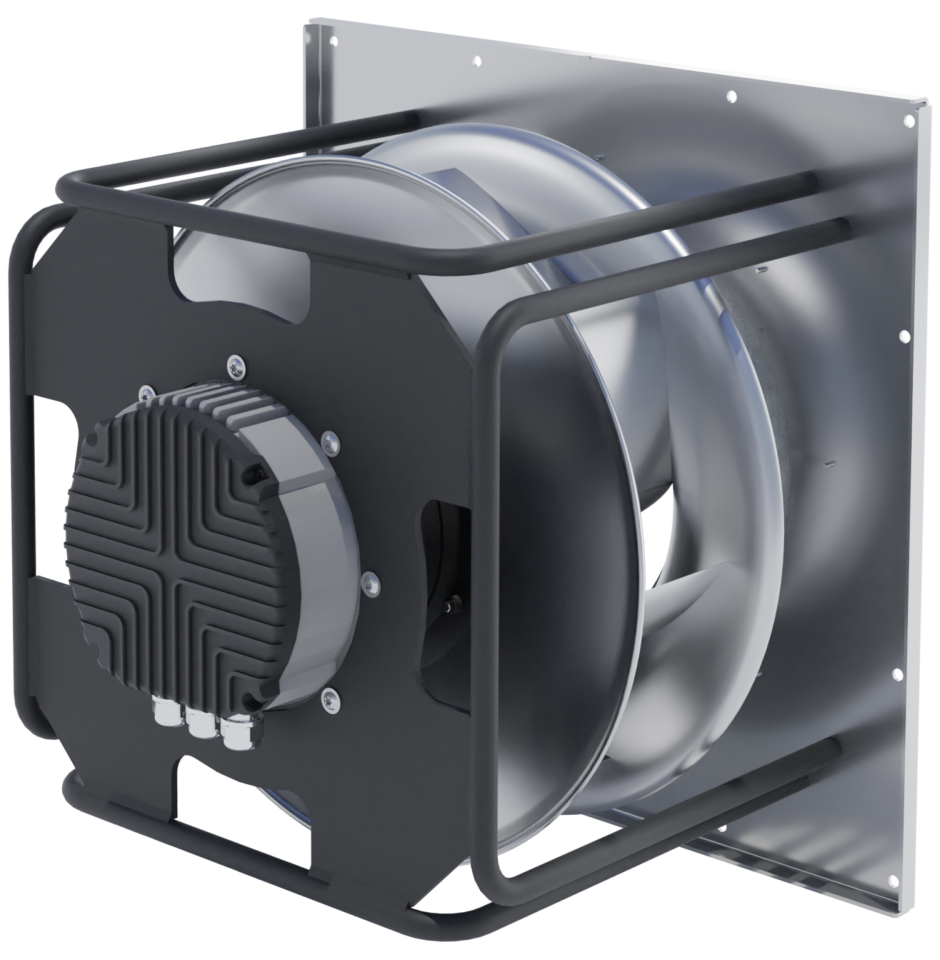
The answer to the above question is simple. The fan we produce. More precisely, a Single Inlet, Single-Width, Backward Curved Radial Fan.
- Impeller, fully integrated with the Electronically Commutated Motor.
- SISW – Single Inlet, Single Width – indicates the difference between this type of fan and from DIDW type (Read the whole story of the AHU fan transformation in the DIDW to EC article),
- BC – Backward Curved – because of the direction of the fan blades’ inclination. Blades are mounted in such a way, that the trailing edge of each of them points direction opposite to the impeller rotation spin.
- EC – Electronically Commutated Motor – simply, because of this very, cutting-edge motor type applied.

To simplify, all of the above definition is commonly known as EC-FAN – an integrated, factory-assembled fan-set, ready to run just after installation. It is a highly specialized fan designed for use in air handling units and Roof-Top devices, for which simplicity of construction combined with reliability and economy of operation are crucial.
Understanding the Fan Operations Principles
Now, that we know what type of fan we are dealing with, it’s time to understand the principles of its operation. More precisely – how does the electricity turn into airflow?
Admittedly, from a didactic point of view, explaining how electrical power supplied to a fan is converted into airflow would be very difficult. it turns out that it is much easier to explain it the other way around, i.e. how the airflow through the fan affects the electrical power consumption of the entire device. So let’s start by specifying what is the final effect of the Fan operation in general.
The product of the fan
The vast majority of us, when asked what is actually a direct product of the fan’s operation, will unhesitatingly point to airflow. In general understanding, this is of course true, but when analyzing the operation of the fan at our level of detail, some clarification is necessary here.
Starting from the obvious statement that the flow of gas (in our case the air) is almost always forced by the pressure difference, the conclusion arises that it is the gain in air pressure that is the essence of the operation of this fan. In other words – To force the airflow, our fan must locally generate its positive pressure on the discharge side and negative pressure on the suction side. As a result of this pressure difference, air begins to flow in the system (air handling unit and ducts connected to it).
So we have a fan operating at two key fixed parameters: airflow and static pressure gain. Interestingly, the result of multiplying these two parameters together gives a certain value expressed in Watts:
V*∆p = [m³/s]* [Pa] = [m³/s]*[N/m²] =[J]/[s]=[W]
It follows that by knowing the airflow flowing through the fan with the simultaneous gain of the static pressure, we can determine the so-called Useful power of the fan. This is the power transferred directly to the ventilation system (air handling unit, Rooftop device with all connected ventilation ducts).
Stages of power transmission
It turns out, however, that generating this useful power is not equal to the power we need to deliver to our EC fan. Based on the laws of physics, which beyond any doubt excludes the existence of the Perpetuum Mobile, it remains obvious that the power supplied to our fan to generate the necessary useful power will be greater than it. Question: how much greater?
Although the calculation of the useful power of the fan based on the above formula is very simple, determining the total power of the specific electrical power consumed by our EC-FAN at a given point of its operation remains a bit more complicated. Between both powers – let’s call them input and output power, we have two key elements, in which power transformations from one form to another take place.
- The first one is (as announced – going “upstream” with our analysis, so that it is easier) the fan impeller itself, which must be mechanically driven in order to be able to rotate and perform its task. The source of this drive is, of course, the EC motor, which provides it with mechanical power, in this case, is the product of angular velocity and torque (multiplied by each other). Of course, the mechanical power delivered from the motor to the impeller will be slightly greater than the useful power discussed earlier.
- The second element is, of course, the motor itself, in which the output mechanical power (transmitted to the fan impeller) is generated from the electrical power supplied to it (in this case, being the product of the Voltage and the Amperage of supplied current – again multiplied by each other – to put it simply). And of course, same as before, the electrical power consumed by the motor always remains greater than the mechanical power produced by it.
Overall static efficiency of the EC-Fan
Looking at the EC fan as a comprehensive device in which the electrical power supplied is first converted into mechanical power (supplying the impeller) and the into useful power – the question arises about the energy efficiency of this system. In our case, this efficiency is a value expressed as a percentage, which is the ratio of the useful power of our EC-FAN to the electric power delivered to its EC motor. This efficiency is called general static efficiency (due to the fact that one of the useful products of its work is the static pressure gain – as opposed to velocity pressure). More interestingly, this value is never constant. it changes depending on the operating point of our EC-FAN, which consists of its air flow rate and increase in static pressure.
Reading the EC-fan specification
What’s more, all the key values describing the operation of the selected fan model at a given point are precisely determined by our selection program and marked on charts. Yes… Charts – in the plural. Let’s have a look at the meaning of the information plotted on each of them, one by one.
Static pressure gain
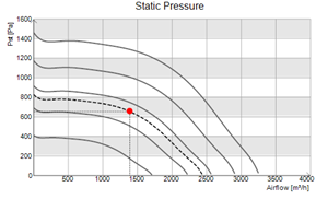
The static pressure diagram is the basic one, where the fan operating point is described as the relationship between the airflow and the generated static pressure increase at a given speed. How this point would change (rotations = constants) is shown by the dashed curve, especially distinguished from all constant-speed curves (solid lines).
The static pressure char is the base one, where the fan operational point is plotted as a function of static pressure.
Let’s take a look at the individual curves plotted on the graph and their meaning (250 mm fan with 0.75 kW EC motor).

Input power
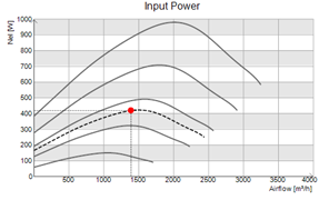
This is a graph showing the change in input (electrical) power as a function of the change in airflow for constant fan revolutions).
In our case (1,390 m3/h / 655 Pa), the power consumption is close to the maximum value for a given fan speed. To answer whether this is good or bad, it is necessary to check what the last graph shows.

Static Efficiency
This is the last chart that closes the whole reliable transfer of information about the selection and operation of our fan at a given point.
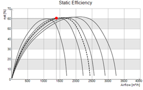
It shows the change in static efficiency, i.e. the efficiency of converting the supplied electric power into the useful power of our EC-FAN, depending on the airflow at constant revolutions. And here, the more (higher) the better, of course..

Conclusions of 3 charts analyzed together
It is a perfectly selected fan with attention to ensuring its operation with maximum efficiency, with a considerable power reserve. Fan, selected for long-term use at the maximum ratio of useful power to input electrical power.
Just try our online fans selection tool at https://selection.swissrotors.com

